Blender Training: Lesson 1
Years:
Intro:
Welcome to Blender! Blender is a free and open-source application for creating 3D graphics, used by millions of hobbyists and businesses across many different industries. Although it’s free to own, Blender is somewhat unique in the world of free and open source software in that it is a serious competitor with its expensive commercial counterparts. Blender is already used widely in the film, gaming, and architectural visualization industries, and its market share is only growing. You can get the latest version of Blender for free here:
https://www.blender.org/download/
Go ahead and install Blender to get started. Blender’s User Interface can be intimidating for first-timers. Below you’ll find a quick explanation of its main elements. But don’t worry about it too much; over the course of these lessons, you will learn the interface a little bit at a time as it becomes relevant.
The User Interface

3D Viewport: The 3D viewport is the portal through which you view 3D space in Blender, like a camera that you look through.
3D Cursor: A utility which acts as a placeholder for a point in space, which can be used by various commands in Blender. For example, a common use case is to change an object’s origin by moving the 3D cursor to the desired location and then using the Set Origin to 3D Cursor command.
Workspaces: These are preset arrangements of menus that are useful for different tasks. For example, the Shading workspace eliminates the Timeline and adds the Shader Editor, UV Grid, and File Browser menus.
Display Settings: Here you’ll find settings to control how objects appear in the viewport, and the User Interface overlays that are displayed. The “Face Orientation” setting in the “Overlays” Dropdown menu is especially useful for troubleshooting strange behavior in a mesh.
Outliner: This is a list of all of the objects in the scene. Objects are organized into Collections. These are like filing cabinets for Blender objects. Each object can be expanded to show the hierarchy of parent / child relationships.
Properties Panel: You can find a bunch of different scene settings here, and different properties panels depending on what kind of object you have selected. For our purposes, the most important panels are the Modifiers panel (the blue spanner) and the Object panel (the orange square).
Timeline: The 4th Dimension in Blender! The timeline is used for animation, some simulations, and video editing. The Timeline can be used to play forward, backwards, loop, and move to different points in time.
Before you start on Lesson 1, I encourage you to take the time to review this list of common commands and practice navigating the viewport.:
https://faesite-72b8257b-666e-43f2-af84.onrender.com/docs/blender-commands/
Because modeling can at times be a very manual and repetitive process, Blender expects the user to rely heavily on Keyboard shortcuts in order to be efficient. However, you don’t have to memorize this list. I will call out the hotkeys as we use them. Before you know it, you’ll be using them without thinking.
Lesson 1
Modeling an Apple:
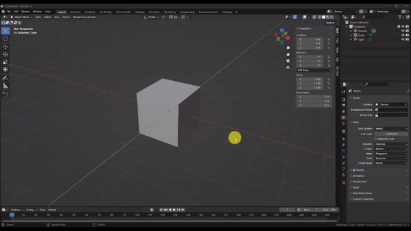
Step 1. When you start a new session of Blender, you begin in “Object Mode.” This is an interaction mode designed for arranging a scene by positioning and orienting collections of 3D models, lights, cameras, and other utilities. To directly edit a 3D model (called a “mesh object”), you must enter “Edit Mode” on the mesh object you wish to work on. Let’s do that now.
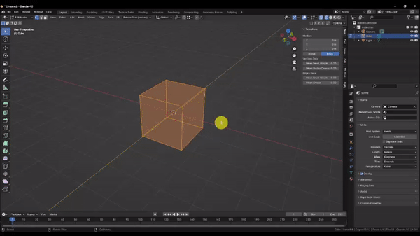
Select the Cube at the center of the scene by Left Clicking it (selected objects are outlined in orange), then press Tab to enter Edit Mode.
Once in edit mode. you will notice that the entire cube is now orange. The cube’s mesh is made up of 3 different selectable entities: Vertices, Edges, and Faces.
Vertices define a single point in 3D space, and represent the corners of the cube.
Edges Connect 2 vertices. Press Z and choose “Wireframe” from the radial menu to see the Model Edges more clearly.
Faces are created from 3 or more edges and define the basic building block of 3D graphics. These are what the software will actually render and shade to create the illusion of a 3D Object on your computer screen.
These 3 entities can be moved, created, and destroyed to create any shape you can imagine.
Step 2. To start with, press Numpad 1 to snap to the front Orthographic view.
In Blender, you view the 3D scene through a virtual camera that tries to approximate how the human eye sees the world through a physical camera lens. By default, the virtual camera renders more distant objects to appear smaller to simulate perspective. The Orthographic view eliminates this perspective distortion so that all shapes appear at their true relative size. This is why our 3D cube now appears flat. Not only are we viewing the cube at a perfect front-facing angle, but the more distant Edges in the back which would normally appear slightly smaller, now appear at the exact same size as the front Edges. They’re still there, but are perfectly occluded by the front Edges.
Let’s begin editing the shape of the cube mesh.
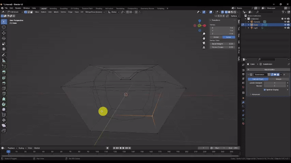
Press Ctrl + R to activate the Loop Cut command, and hover your pointer over the right edge of the cube. The line that appears is a preview of the new edges and vertices that will be cut into the faces of the cube to divide them in two.
The Loop Cut command divides a chain of 4-sided faces (or “Quads”) by cutting new edges along the entire chain. You can’t see it because of our Orthographic camera view, but these new Edges will wrap around the entire cube.
Left Click to Confirm the Loop Cut Command.
The Loop Cut command automatically activates an Edge Slide command, giving you the option to position your new edge loop. We will keep the default edge loop position for now. Press Esc to cancel the Edge Slide command.
The new edge loop is automatically selected for us. Press S to Scale the selection and drag your mouse away toward the edge of the screen to make the mesh wider about the middle as shown. Then Left Click once to confirm the Scale operation.
With your edge loop still selected, press G to Grab the selection, then press Z to lock to the Z axis. Pressing the X, Y, and Z keys while carrying out certain commands will often allow you to limit the affect of the operation to those axes. In this case, by locking to the Z axis, we can be assured that our selection will only move up or down. Drag your mouse towards the top of the screen and position the edge loop roughly as shown to achieve a more apple-like shape.
Step 3. By now, you’re probably thinking that you have to squint really hard to see anything resembling an apple. So let’s fix that with one of the most powerful and commonly used tools in Blender: the Subdivision Surface modifier.
A modifier is a special tool in blender that you attach to an object in your scene, and which can simulate various procedural effects. Modifiers are non-destructive, which means that their affects are easily modified or erased as you go without causing you to lose any work. The affects of a modifier only become permanent when the user chooses to apply the modifier.
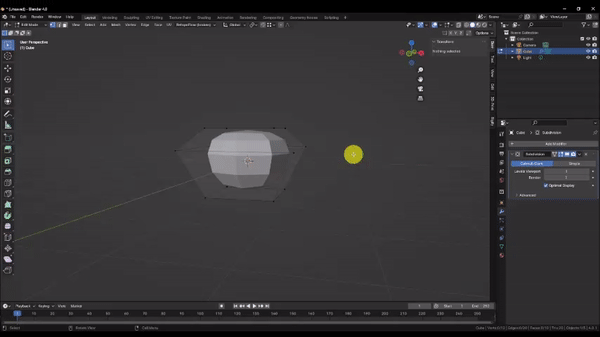
Navigate to the “Modifiers” tab in the Properties panel by Left Clicking the blue spanner icon. Then Choose “Add Modifier” → “Generate” → Subdivision Surface. Press Z and choose “Solid Shading” mode and orbit to a 3D view to see the result.
Now you should see a shape that’s beginning to more closely resemble an apple within your wire mesh. The Subdivision Surface Modifier increases the resolution of your mesh, by interpolating between the existing geometry and dividing it into smaller pieces. The operation is repeated according to the value set for the “Viewport Levels” parameter. Increasing this value will make your mesh finer and finer, and your model will appear smoother.
IMPORTANT:
The Subdivision Surface modifier increases the number of polygons that the computer must draw to the screen by 4^n where n = the levels value. Although Blender can safely draw a few million polygons on most machines, consider that if you were to add a Subdivision Surface modifier to a base mesh consisting of 100,000 polygons, Blender would be asked to render 102,400,000 polygons. This would undoubtedly crash the program, causing you to lose work! Proceed with caution when subdividing meshes with large numbers of polygons.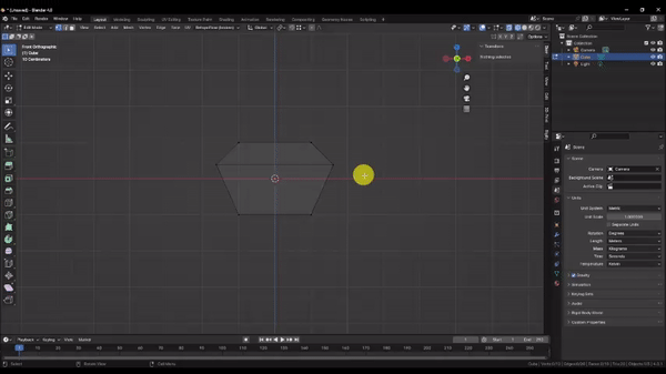
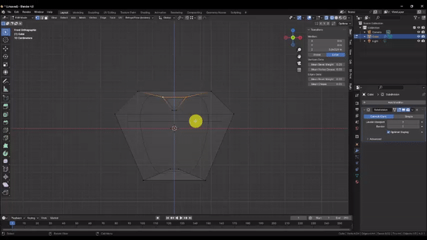
Step 4. Because the Subdivison Surface modifier has not been applied, it is only simulating the effect that you see. This is why you can’t access the vertices, faces, and edges of the new geometry, even in Edit Mode. Instead, we exert control over the new geometry by changing the original geometry from our modified cube (or “base mesh”).
Select the 4 vertices that make up the top face of the base mesh. by holding Shift and Left Clicking each of them. This allows you to select multiple entities.
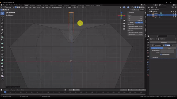
Press i to activate the Inset Face command. and drag the pointer towards the middle of the screen as shown. Left Click to confirm the operation.
With your vertices still selected, press G to activate the Grab command, then press Z to lock to the Z axis, and drag the vertices down as shown to create the divot at the top of the apple.
Step 5. Let’s finish refining the shape. You may have noticed in the last step that the vertices we were manipulating appeared to pull down inside of the faces of our subdivision surface model. To help us keep sight of our base mesh geometry, Press Z and choose “Wireframe” mode.
Select the vertices that make up the bottom face of your apple by holding Shift and Left Clicking each of them. Then press Numpad 1 to snap to the Front Orthographic view.
With the vertices still selected, press G to activate the Grab command, Z to lock to the Z axis, and drag the vertices down as shown to lengthen the apple. Left Click to confirm the operation.
Orbit the camera to a 3D view, then press S to activate the Scale command, and drag your pointer toward the center of the screen to taper in the bottom of the apple. Left Click to confirm the operation.
Just like we did for the top divot, press i to activate the Inset Face command, drag your pointer toward the center of the screen, and Left Click to confirm the operation.
Finally, Press G to activate the Grab command, Z to lock to the Z axis, and drag the vertices up as shown. Left Click to confirm the operation.
To see your work, press Z and choose “Solid” in the radial menu. Then increase the “Levels Viewport” value to 3 in the Subdivision Surface modifier.
Step 6. Now we’ll make the stem. Press Z and once again choose “Wireframe” from the radial menu. Then press Numpad 1 to snap to the Front Orthographic view.
In Blender, your geometry doesn’t have to all be connected. Sometimes it’s useful to separate it to save time and polygons. Doing that here will save us some work fighting with the Subdivision Surface modifier’s smoothing algorithm.
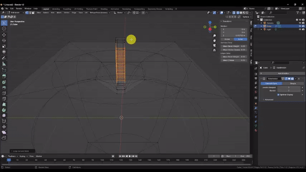
Left Click and drag to Box Select the 2 inner vertices of the stem divot as shown. Using Box Select in Wireframe mode is an effective way to grab ALL of the desired vertices. Remember that there are actually 2 in the back that we can’t see.
Now, Hold Shift and press D to activate the Duplicate command. This creates a copy of the selected vertices, and automatically starts a Grab operation with the new selection. Press Z to lock to the Z axis and drag the selection up slightly. Left Click to confirm the operation.
With the vertices still selected, press E to activate the Extrude command and drag the extruded geometry up as shown to create the stem. Left Click to confirm the operation.
Step 7. We have the start of our stem, but the ends are much too round and elongated. This is because of how the Subdivision Surface modifier is dividing the geometry. To control the sharpness of a subdivided edge, we can reduce the interpolation distance by adding additional edge loops to closely reinforce the edge. These are commonly called “supporting edge loops.”
Hold Ctrl and press R to activate the Loop Cut command, then hover over the right edge of the stem as shown and Left Click to confirm. Press Esc to cancel the edge slide.
With the new edge loop still selected, hold Ctrl and press B to activate the Bevel command. This will split your edge loop into 2 edge loops evenly in both directions. Drag the pointer toward the edge of the screen as shown until you have 2 new edge loops positioned very close to the edge of your stem. As you approach the edge, you should notice the Subdivision Surface geometry becoming sharper.
We will want to give this stem a natural-looking bend, but there are no true curves in 3D graphics, so the only way to accomplish this is to add more edge loops to work with.
Hold Ctrl and press R once again to activate the Loop Cut command. Then hover over the edge of the stem as shown, but don’t confirm the operation just yet. Instead, Scroll with your Mouse Wheel to adjust the number of edge loops to add, until the preview is showing 5 new edge loops. Then Left Click to confirm the operation and press Esc to cancel the Edge Slide.
Step 8. In principle, more geometry affords us more control over the shape of your mesh. However, in practice, too much geometry can quickly become unwieldy, time-consuming, and impractical to manipulate effectively. When necessary, Proportional Editing can help you shape large numbers of vertices at once. When enabled, Proportional Editing causes your Grab, Rotate, and Scale operations to also impact nearby vertices within a certain radius, according to a falloff curve.
Select the top face of your stem by holding Shift and Clicking each of the 4 vertices.
Left Click to activate Proportional Editing near the top middle of your screen, then in the “Proportional Editing Falloff” dropdown menu, choose the “Sphere” option for the falloff curve, and check the box for “Connected Only.” This will prevent the falloff from affecting the apple, since the mesh is not connected to the stem.
With the top of your stem selected, Press R to activate the Rotate command, drag the pointer to influence the rotation angle and Scroll with the Mouse wheel to adjust the Proportional Editing falloff radius. Take some time to observe the combined interaction of these operations. It will likely take a combination of Grab[G] and Rotate[R] operations to achieve a good result, so confirm the operation when you’re satisfied and repeat this process as many times as you need to nudge the stem into shape little by little.
To see your work, press Z to switch back to “Shaded” mode and then press Tab to switch to Object Mode.
Congratulations! You’ve completed Lesson 1!