Blender Training: Lesson 3
Years:
Lesson 4:
Modeling the Cockpit
Step 1: Click the “Transform Pivot Point” dropdown box and set it to 3D Cursor. This will make it easier to resize the reference image. Then Press Shift + C to ensure that the 3D cursor is at the scene origin.
Step 2: Press Numpad 3 to snap to a Side Orthographic view. Then, in the “Add” Dropdown box, choose Image → Reference, browse to Airplane1.jpg, and click Load Reference Image.
Step 3: Press Z and change your viewport shading to Wireframe. Then Left Click to select the image, and in the properties panel under the “Data” tab, tick the “Opacity” check box and and set the opacity value to 0.2. This will make the reference image semi-transparent so we can better see our model edges.
Step 4: Grab [G] and Scale [S] The image as needed to match the size of the Cabin section we modeled. Align the image so that the first passenger window is positioned within the Cabin section; don’t worry if the window cutouts in your model don’t match the reference. Try to align the image so that the spaces between the front and rear edges of the Cabin section and the nearest windows are equal.
Step 5: Now we’ll establish a Top View reference for our model.
Press Shift + D to duplicate the Reference Image, then press Esc to cancel the move operation.
With the Reference Image still selected, press R to activate the Rotate command, and Y to lock rotation to the Y axis. Then enter 90 on the keyboard to rotate the image 90 degrees about the Y axis.
Press Numpad 7 to enter a Top Orthographic view.
Grab [G] the image, then press X to lock movement to the X Axis, and position the Top view in the Reference Image to align with our model. Do not use the Scale command in this step; we already set the size of the image in the last step.
Step 6: Let’s clean up the work space a bit.
Orbit the camera to get a 3D view of the work space, then move the 2 Reference Images clear of the model.
Grab [G] the Top View image, press Z to lock it to the Z axis, then drag it down below the model.
Grab [G] the Side View image, press X to lock it to the X axis, then drag it behind the model.
Step 7: In the Outliner, Right Click an empty area and choose “New Collection.” Then, Left Click the collection and press F2 to rename it to “Reference.” Collections are like filing cabinets for Scene Objects that allow us to better manage Object visibility. To add the reference images to the collection, hold Ctrl and Left Click all 3 Image Objects, (By default, they’re named “Empty”) and drag and drop them over the “Reference” Collection.
Lastly, select the “Reference Collection,” and in the “Collection” tab of the properties panel, uncheck “Selectable.” This will disable object selection for everything within the collection, and will prevent us from accidentally moving the Reference Images.
Step 8: We can organize the rest of our scene objects while we’re at it. Hold Ctrl and Left Click the Camera and Light, then press M and choose “New Collection,” and name it “Lights & Cameras.” That leaves only the 2 Objects that make up the Cabin, which are already in a Collection. Rename it to “Cabin,” by Left Clicking it and pressing F2.
Now let’s create a new Collection for the Cockpit by Right Clicking an empty spot in the Outliner, choosing “New Collection,” and naming it “Cockpit.” Left Click the newly created Collection to make it the active Collection where new Objects will be stored by default.
Step 9: To ensure that the Cockpit matches up exactly with the Cabin section, we can Duplicate the Cabin section profile to use as a base and work from there.
Left Click the Cabin section to select it and then press Tab to enter Edit Mode.
Select the outer most ring of edges by holding Alt and Left Clicking an edge. Hold Shift and repeat as needed to select all of the outer edges.
Press P and choose “By Selection” to copy these vertices into a new Object.
In the Outliner, drag and drop the newly created Object into the “Cockpit” Collection, and then Left Click the eye-shaped icon to the right of the “Cabin” Collection. This will hide the Cabin section so we can focus on the Cockpit.
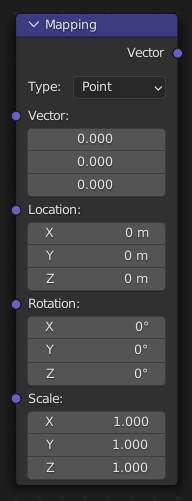
Step 10: Click the “Transform Pivot Point” dropdown box and set it back to Median.
Step 11: Press Numpad 3 to enter a Side Orthographic view, then select the Object in the “Cockpit” Collection and press Tab to enter edit mode.
Press A to select all of the vertices, and Extrude [E] towards the front of the plane. Try to align your first extrude with the near edge of the door frame in the reference . Repeat this process for the far edge of the door frame. Grab [G] and Scale [S] your selection as needed to match the shape of the cockpit in the reference. Remember that you can hold shift while positioning your vertices to achieve finer control.
Continue to Extrude [E], Grab [G], and Scale [S] your selection up to the nose of the Cockpit as shown. If you need additional edge loops to match the curvature of the reference, you can add them with Ctrl + R. Don’t get carried away, though. Too many edge loops will become a hassle to manage, and we can always smooth out our shapes with a Subdivision Surface modifier later on.
Step 12: To fill in the end cap, orbit the camera around so you can see better, then with the vertices at the end of the nose selected, press the Space Bar to bring up your Command Lookup window, and search for “Grid Fill.” Grid Fill attempts to neatly fill a selection of vertices with 4-sided faces (Quads). Use the “Span” value in the context menu to adjust the number of desired faces, and the “Offset” value to rotate the pattern.
Step 13: We need to form these vertices into an elongated dome to match our references. To do this, we will use a tool called Proportional Editing, which allows us to manipulate a small selection of vertices, while also influencing nearby vertices according to a fall-off pattern. But first, we need to temporarily separate our mesh at the base of the cone, to prevent Proportional Editing from affecting anything we don’t want it to.
To do that, we will select the edge loop that represents the base of our nose cone by holding Alt and Left Clicking an edge, and then pressing H to hide those vertices.
Now, activate proportional editing mode, select the “Inverse Square” falloff pattern from the dropdown box, and then tick the “Connected” checkbox. When “Connected” is checked, Falloff will only affect connected geometry.
With proportional editing enabled, select the middle two vertices, Press G to grab, press Y to lock to the Y axis, and drag the vertices towards the nose. You can Scroll with the Mouse Wheel to increase or decrease the Falloff radius. When you’re satisfied, hold Alt and press H to unhide the vertices we hid earlier.
Step 14: To Finalize the overall shape of the cockpit, Press Numpad 7 to snap to the Top Orthographic view, select the edge loop at the rear of the cockpit and press H to hide it. This will prevent unwanted changes to the interface with the Cabin section.
Scale [S] edge loops to match the reference. Be sure to lock to the X axis when scaling so as not to affect the alignment of the mesh with the Side View reference.
You can also improve your surface topology with the “Smooth Vertex” command by pressing A to select all of your vertices and then pressing Ctrl + V
When you’re happy with the mesh, press Alt + H to unhide the vertices we hid earlier.
Step 15: Unlike the Cabin windows, the Cockpit windows represent a unique challenge in that they wrap around the curvature of the nose, and cut inwards normal to the surface. Therefore, our cutting Object must do the same. Press Tab to exit to Object Mode, then insert a plane with Add → Mesh → Plane, and in the “Add Plane” context menu, set the Y offset to -2
Press Tab to edit the plane, Rotate [R] it, press Y to lock to the Y axis, and enter 90 on the keyboard to rotate the plane 90 degrees about the Y axis.
Toggle off Proportional editing, toggle on “Snap,” then under the “Snapping” dropdown menu, Left Click the “Face Nearest” option, and the “Rotate” and “Scale” options.
The “Face Nearest” option automatically snaps the vertices in your selection to the nearest face belonging to another Object. We can use this to conform our plane to the curvature of the cockpit.
Grab [G] the vertices and hover over the Cockpit section. Your vertices will become obscured, but don’t worry; they haven’t disappeared.
Step 16: To cut out the window, our mesh needs thickness. We can accomplish this with some modifiers.
In the modifiers tab of the Properties panel, choose Add Modifier → Generate → Subdivision Surface
Left Click the “On Cage” option to preview the modifier while in Edit Mode and the “Realtime” option to disable visibility. We will use this later.
Set the “Levels Viewport” value to 2
choose Add Modifier → Generate → Solidify
In the Solidify modifier, Left Click the “On Cage” option to preview the modifier while in Edit Mode.
Check the “Even Thickness” box, then expand the “Normals” section and check the “High Quality” box.
Set the “Thickness” value to 0.5 and the “Offset” value to -0.6. Feel free to play around with these values to see how they affect the result.
Since our windows will be symmetrical, we can cut our workload in half and help with alignment by also adding a Mirror Modifier under Add Modifier → Generate → Mirror
Step 17: With snapping enabled you can begin to Grab [G] Individual vertices and move them along the curvature of the cockpit.
Press Z to bring up the Shading menu and switch back and forth from Solid to Wireframe. Refer to your Side reference with Numpad 3 and Top reference with Numpad 7 to help you size and position your windows. Note that the projection in our reference images is not perfect, so it may not be possible to perfectly align with the reference in both views. Just try to achieve something that looks good to you.
You can select the entire plane and press Shift + D to duplicate it to add the other window planes, and continue this process.
Step 18: Use Ctrl + R to add Edge Loops to our windows as shown. You can Scroll with the Mouse Wheel to increase or decrease the number of edge loops to cut. Adding these extra vertices helps the windows conform better to the surface of the cockpit, and allows us to further refine the shapes. We will address the rounded corners in the next step.
Step 19: Left Click the “Realtime” option to unhide the Subdivision Surface modifier we added earlier. You can see how this has helped to smooth the shape of our windows, but the effect on the corners is a bit too strong.
We can address this by assigning a “Crease” value to the corner vertices, which tells the Subdivision Surface modifier to adjust its smoothing algorithm in the areas we designate.
Use Shift + Left Click to select the corner vertices of your windows that need sharpening, then in the “Item” tab near the Outliner, set the “Vertex Crease” value to 0.30. Feel free to play with this value to see the effect.
Step 20: When you’re happy with the shape of your windows, press Tab to exit edit mode.
Then Shift + Left Click the Cockpit section and under the “Edit” tab near the Outliner, Left Click the Brush Boolean “Difference” option to cut out your windows. You should see deep recesses where the windows aught to be. This is because we haven’t yet given a thickness to our cockpit, so there are no interior faces to cut through to make a hole.
With the cockpit section selected, in the Modifiers tab of the Properties panel, choose Add Modifier → Generate → Solidify.
Like before, check the “Even Thickness” option, then expand the “Normals” section and check the “High Quality” option. Since we’re working in Object Mode here, we don’t need the “On Cage” option this time.
Orbit around so you can see the Cross Section reference image.
Then set the “Offset” value to -1, and adjust the “Thickness” value until it closely matches the reference.
Step 21: Now we’ll make the door.
Choose Add → Mesh → Plane to insert a mesh, Press Z to enter Wireframe Mode, and Press Numpad 3 to snap to the Side Orthographic view.
With the plane selected, Grab [G] and press Y to lock it to the Y axis, then drag it towards the nose until the small orange dot that represents the plane Origin is centered on the cockpit door in the reference.
Press Tab to go into Edit Mode, then toggle off the “Snap” option.
Rotate [R] and press Y to lock the selection to the Y axis, then enter 90 on the keyboard to rotate the plane 90 degrees along the Y axis.
Now Grab [G] and Scale [S] the vertices to match the reference.
Press Ctrl + R to add edge loops as shown. You can Scroll with the Mouse Wheel to increase or decrease the number of Edge Loops to cut.
When you’re done, press Z to change back to Shaded Mode, then orbit the camera to a 3D view.
Press A to select your entire mesh, Grab [G] and press X to lock it to the X axis. Then drag the selection outside of the cockpit toward you, and press Tab to enter Object Mode.
Step 22: Although, we could use the same approach we used for the windows to cut out our door frame, there’s an important modifier you should know about that we’ll use instead.
With your door selected, under the “Modifiers” tab of the Properties panel, choose Add Modifier → Generate → Subdivision Surface and set the “Levels Viewport” value to 2
Choose Add Modifier → Deform → Shrinkwrap, then Left Click the “On Cage” option, and under the “Wrap Method” dropdown menu, choose “Project.”
Check the “Negative” box, and Left Click the “X” option.
Where it says “Target,” Left Click the Eye Dropper Icon. This type of box takes a mesh Object in our scene as the input. With your Eye-Dropper tool activated, Left Click on the Cockpit section to make it the Shrinkwrap Target.
Your mesh should now be wrapped to the side of the cockpit.
Just as with the windows, we need to thicken this mesh to use it in a Boolean operation.
Choose Add Modifier → Generate → Solidify, then Left Click the “On Cage” option
Check the “Even Thickness” box, then expand the “Normals” section and check the “High Quality” box.
Set the “Thickness” value to 0.5 and the “Offset” Value to -0.5.
Now, let’s round the corners of our door.
Press Z to go into Wireframe Mode, then press Numpad 3 to snap to the Side Orthographic view, and press Tab to enter Edit Mode.
Shift + Left Click each of the corner vertices, press Ctrl + B to bevel, and then V to switch to vertex bevel mode. Scroll with your Mouse Wheel to increase the vertex count on each corner to 3, then drag until the corner radii match your reference.
Orbit your camera to a 3D view, Press Z to return to Shaded mode, and press Tab to enter Object Mode.
Step 23: In the Shrinkwrap modifier, Click the small dropdown arrow near the camera icon and choose “Apply.” This finalizes the changes from the Shrinkwrap Modifier to the base mesh.
We can now cut out the door frame, but before we do, press Shift + D and then Esc to make a copy of our cutting tool that we can later use to model the door itself.
Shift + Left Click to select the Cockpit section, and then under the “Edit” tab near the Outliner, choose Brush Boolean “Difference.”
You should now have a door frame cut into the cockpit. However, it is obscured by the door we copied earlier.
Left Click to select the door, then press Tab to enter Edit Mode.
Press A to select the entire mesh, then Scale [S] it slightly to create a small gap between the door and the frame.
Step 24: Lastly, we will create a window in the door. We could use the same method that we used to cut out the windows for the cockpit, but Boolean operations are expensive and we would likely begin to experience performance issues. Instead, we’ll directly edit our mesh to cut out a window.
Press Z to go into Wireframe Mode, then press Numpad 3 to snap to the Side Orthographic view, and press Tab to enter Edit Mode.
Press K to activate the Knife tool and Left Click on each corner of the door window to cut a rectangle into our mesh. Press Enter when you’ve finished tracing the window to confirm the cut.
Select the faces that represent your window, press Delete and choose “Faces”
You will see that the Subdivision Surface geometry behaves erratically. This is because the Subdivision Surface algorithm needs 4-sided faces (Quads) to work correctly, and adding the new vertices for the window, created a number of odd-sided faces (N-gons). To fix this, we will cut new edges between the corners of the window and nearby vertices on the door.
Press Shift + Left Click to select 2 vertices, then press J to join them with an edge as shown.
This improves our Subdivision Surface geometry, but the window corners are now much too rounded. We can fix these the same way we fixed the windows for the cockpit.
Press Shift + Left Click to select all 4 corners of the window, then in the “Item” tab near the Outliner, set the “Vertex Crease” value to 1
Press Tab to enter Object Mode, then Shift + Left Click the Cockpit section. Right Click to bring up the Object menu and choose “Shade Auto smooth” to see the final model.