Blender Training: Lesson 4
Years:
Lesson 4
Modeling the Wings:
Step 1: Before we start modeling the wings, let’s get an idea of what the Cabin will look like at its full length. This will help us see where the wings need to intersect with the model.
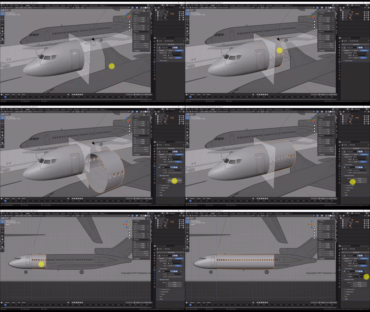
In the Outliner, unhide the “Cabin” collection by Left-Clicking on the eye icon to the right.
Left Click the Cabin section to select it and under the Modifiers tab of the Properties panel, choose Add Modifier → Generate → Array.
In the Array Modifier, under the “Relative Offset” section, change the X value to 0 and the Y value to 1. This should extend your Cabin section. If the cabin duplicates in an inappropriate direction or orientation, try applying the rotation and scale of the cabin section by pressing Ctrl + A and choosing “Rotation & Scale.”
Set the “Count” value to 8.
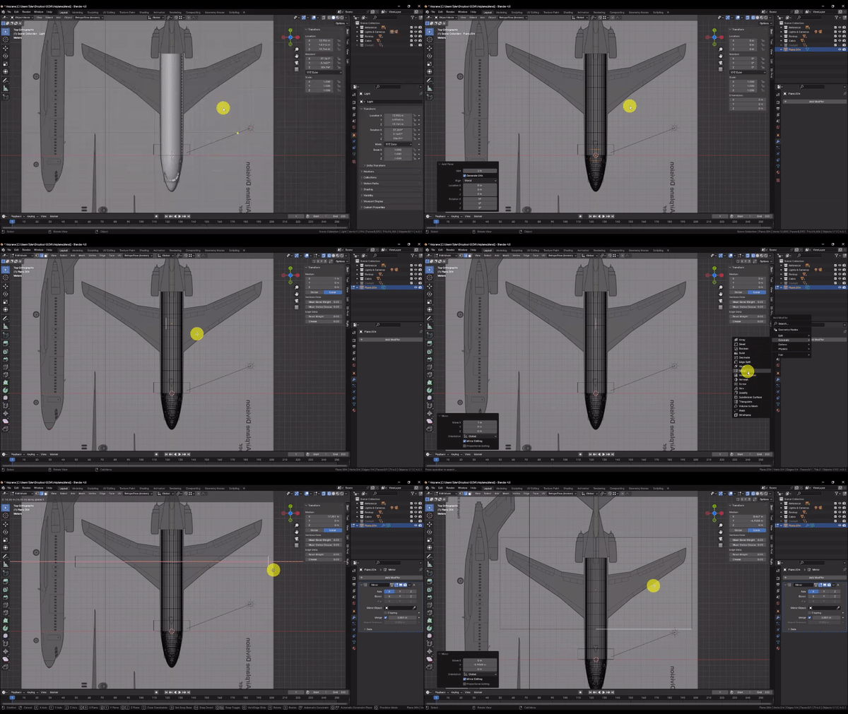
Step 2: Let’s model the wings. Press Shift + C to to ensure that the 3D cursor is at the center of the scene, then press Numpad 7 to snap to the Top Orthographic view, and press Z to change to Wireframe mode.
In the Add menu, choose Mesh → Plane, then Grab [G] it, press Y to lock it to the Y axis, and position it roughly along the middle of the wing width in the reference as shown. Left Click to confirm the command. Then Press Tab to enter edit mode on the newly created plane.
In Edit mode, switch to Edge Select Mode, then Grab [G] the left-most edge of the plane, press X to lock it to the X axis, move your mouse to the right and press 1 on the keyboard to move the edge 1 meter to the right along the X axis. The default size of a newly created plane is 2 meters, so moving the edge 1 meter toward the center effectively splits the plane in half.
With the plane now split in half, under the Modifiers tab of the Properties panel, choose Add Modifier → Generate → Mirror. Now the changes you make to the right side of the mesh will be automatically mirrored to the left.
Finally Grab [G] the top, bottom, and left edge as shown so that the plane fully encloses the wings in the reference, then switch back to Vertex Select Mode.
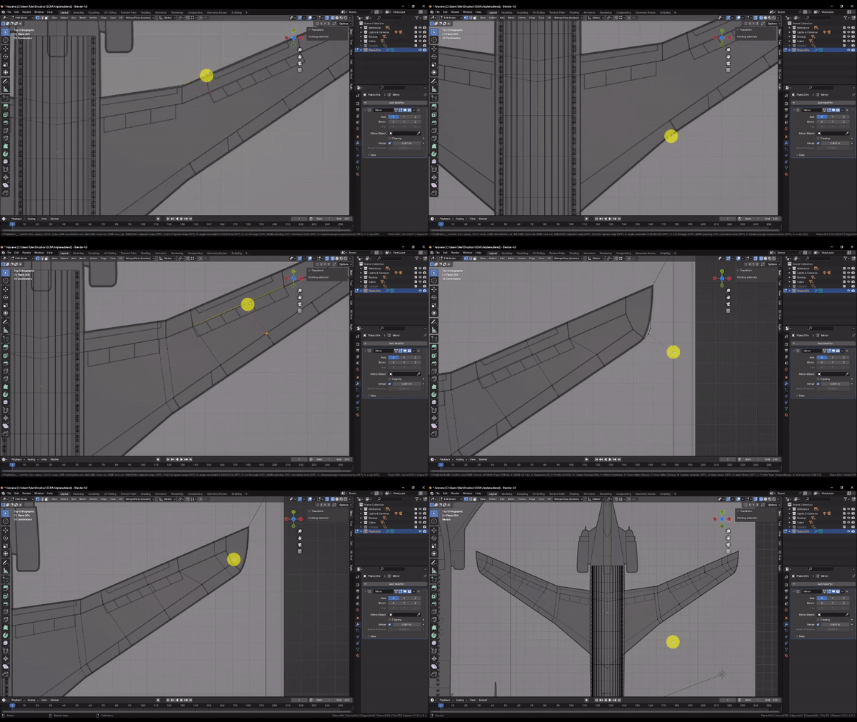
Step 3: Here we will rely heavily on the Knife [K] tool to cut out our wing shape and define the inner edges we will use to create the wing slope.
In Edit Mode, Press K to activate the knife tool and begin tracing the reference by Left Clicking from point to point. You can do this in as many or as few operations as you need to. Simply press Enter when you want to confirm a cut, and K to activate the knife tool once again to continue. Note, if you need to, you can press X, Y, or Z to lock the knife tool to a particular axis.
If your cuts aren’t perfect, you can always switch back to Vertex select Mode, and Grab [G] to move individual vertices to better match the reference. You can also press Delete and choose the “Dissolve Vertices” and “Dissolve Edges” options to eliminate unwanted geometry without destroying faces.
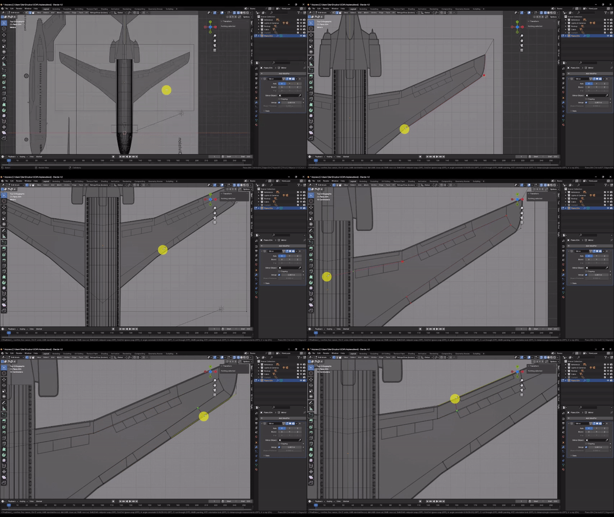
Here, I cut edges across the wings to make all of my interior faces 4-sided (or Quads). Ideal model topology consists of 100% 4-sided faces that align with the flow of the model geometry, and are as uniform and square as possible. This is especially important when modeling an object with a curvy, organic shape, like the 3d curvature of our wings, or when you plan to use the Subdivision Surface modifier.
Step 4: In order to incorporate a cross-sectional curve in our wings, we will need additional interior geometry.
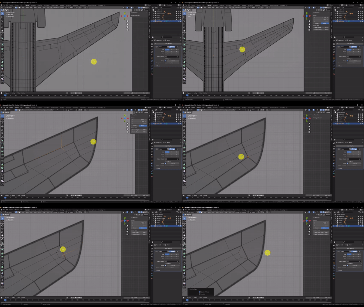
Press Ctrl + R to cut in additional edge loops. You can Scroll with the Mouse Wheel to increase or decrease the number of edge loops to add. Here I’m adding 2. Left Click to confirm the cut, and then press Escape to cancel the Edge Slide operation.
The additional edge loops will help us when we define the curvature of our wing, but upon reaching the wing tip, they become unnecessary and the geometry is more dense then we need.
Use the Knife [K] tool to cut some new edges as shown.
Switch to edge select mode, select the edges at the wing tip as shown, then press Delete and choose “Dissolve Edges.”
This leaves behind a trapezoidal shape, which helps us to achieve more uniform mesh density, while still maintaining good topology conditions. The trapezoid also redirects the “flow” of the geometry so that it better follows the interior edges defined in the reference.
Topology is equal parts art and science, so don’t worry if you don’t yet fully understand the difference between “good” and “bad” topology. It will become clearer with experience.
Step 5: We’re ready to give the wings some thickness.
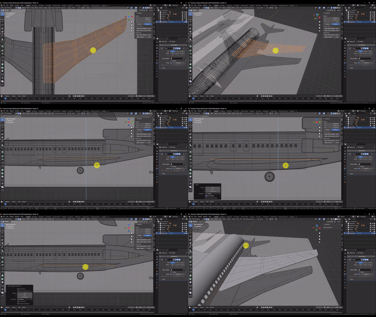
Press A to select the entire mesh, then Press Numpad 3 to snap to the Side Orthographic view, and Z to change back to Solid shading.
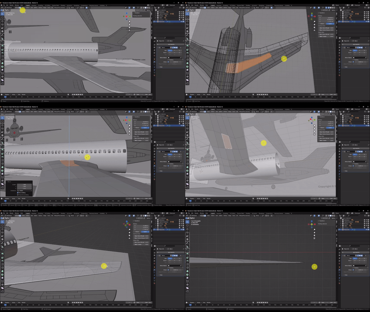
Grab [G] the mesh, press Z to lock to the Z axis, and drag it down to roughly align with the height of the wings in the reference.
Finally, press E to Extrude the mesh, drag down slightly as shown and Left Click to confirm the operation.
Step 6: In the last step, we established the thickness of the wings at the tips. Now we’ll use proportional editing to thicken the wings where they intersect the cabin, tapering towards the tip and the edges of the wings as we go. But before we do, we have to mask off some areas that we don’t want affected by the proportional editing radius.
Switch to face select mode, then hold Shift + Left Click to select the faces along the thickness of the wing, as well as the faces around the edges of the wings as shown. You can add entire face loops to your selection by hovering near an edge of the face and holding Shift + Alt and Left Clicking. Don’t forget to select the top and bottom faces!
When you’re done, press H to temporarily hide the selection.
Select all of the remaining faces that intersect the cabin. I chose to select the top and bottom faces, but if you wish to match the reference, choose the bottom faces only. Then press Numpad 1 to snap to the Front Orthographic View.
Activate Proportional Editing, then under the Proportional editing dropdown menu, choose “Linear” for the falloff type, and make sure the “Connected Only” option is checked.
Scale [S] your selection, press Z to lock to the Z axis, then drag and Scroll with the Mouse Wheel to adjust the proportional editing falloff radius. You should be able to taper the wing thickness as shown.
When you’re satisfied, Left Click to confirm the operation, and turn off Proportional Editing.
Orbit the camera to a 3D view and press Alt + H to unhide the faces you hid earlier to see the result.
Step 7: Now we’ll add a little curvature to the wing profile.
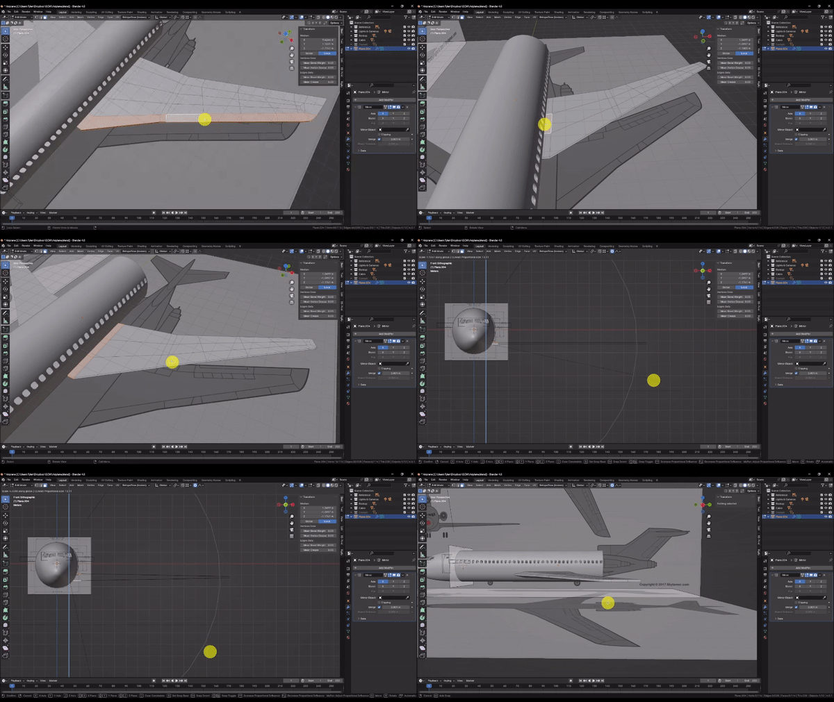
Hold Shift and Left Click to select the interior most faces of the wing on the top and bottom as shown.
Scale [S] them out to make the wings thicker along their center-line. Try scaling top / bottom pairs of faces at different points along the length of the wing to try and match the tapering affect we created earlier.
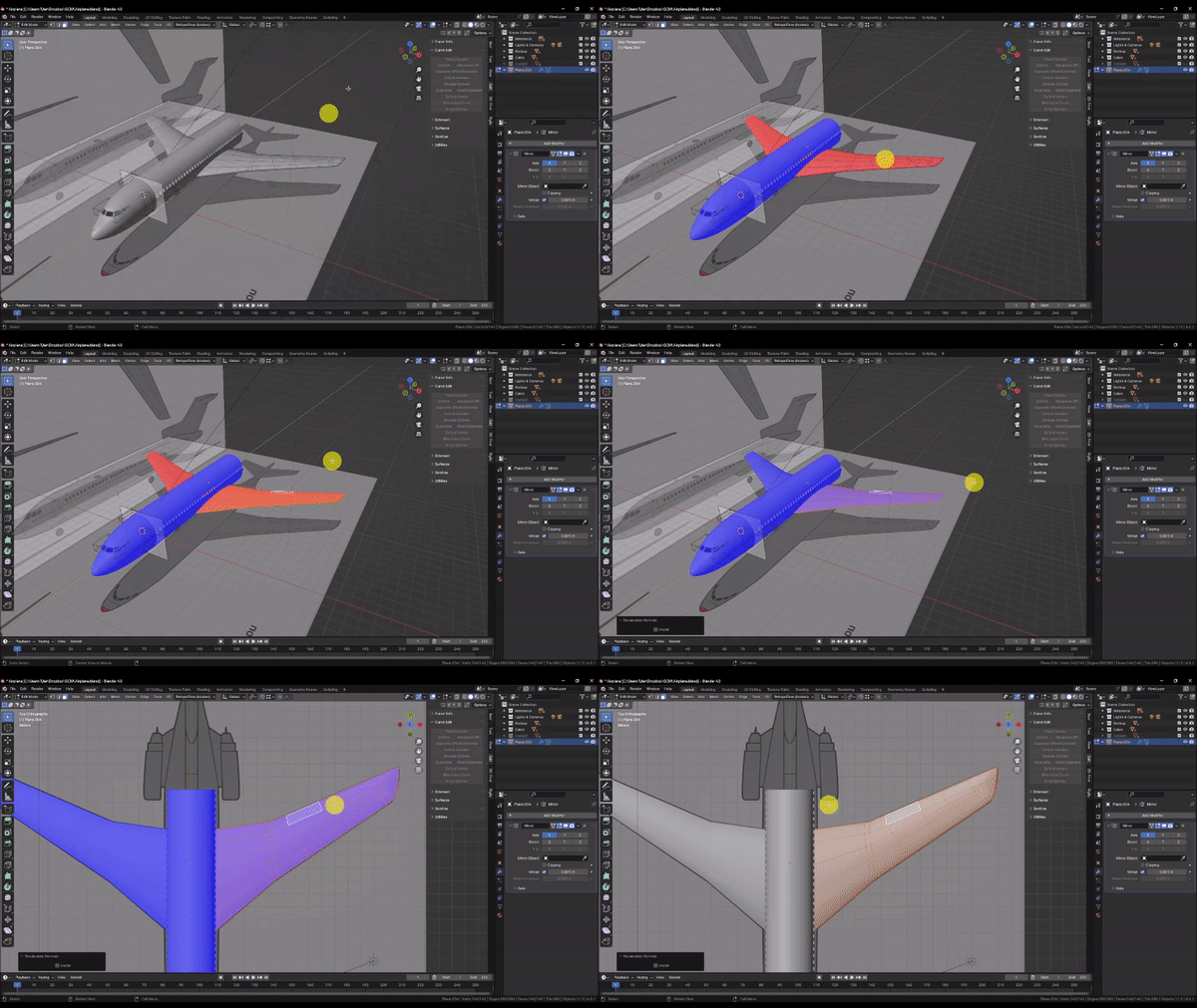
Step 8: Next we’ll cut out the wing flaps to add a little detail. But before we do, let’s quickly check our face “normals” to make sure all is well. A Face “normal” refers to the direction the front of the face is pointing. Each face in a mesh has a front and back face, and its normal direction can change how the software treats it. In most cases, the front faces of a model point in the direction that the model is intended to be viewed from. For example, if a cube is meant to represent a six-sided die, the front faces should point out away from the model. If the cube is instead meant to represent a room interior, then the front faces would point inward, since the model is intended to be viewed from within. Face normals also affect boolean operations, which rely on face normals to distinguish the insides and outsides of the intersecting volumes.
To check our face normals, press Z to ensure you are in Solid shading mode, then check the “Face Orientation” box in the Viewport Overlays dropdown menu.
In general, faces that appear blue are pointing the right way. But if, like me, the faces of your wing are red, that means that the wing is inside out! This likely occurred when we first extruded the thickness.
To fix this, press A to select the entire mesh, then press Alt + N and choose “Recalculate Outside.” Confirm that your face normals are now correct, then uncheck the “Face Orientation” box in the Viewport Overlays dropdown menu.
If you find that certain commands aren’t working as you expect, it’s always a good idea to check your normals!
Step 9: Now that our normals are fixed, we can proceed with cutting out the wing flaps.
Press Numpad 7 to snap to the Top Orthographic view, then press Shift + Left Click to select the faces that represent our wing flaps as shown.
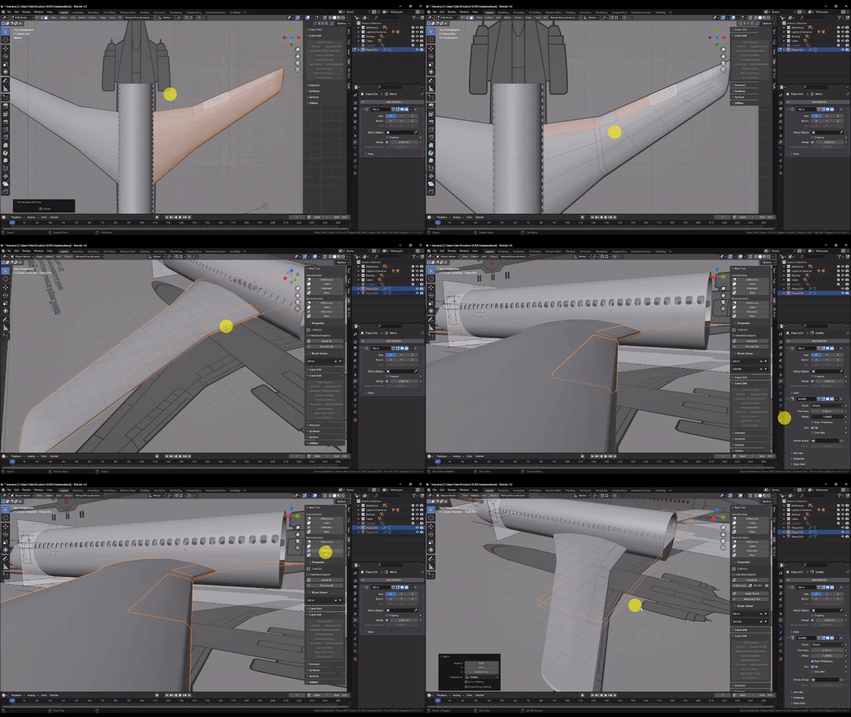
Duplicate [D] the faces, then press P and choose “Selection” to move them into a new scene object. Press Tab to exit to Object Mode
In the Outliner, select the object that represents your wing flaps, then in the Modifiers tab in the Properties panel, choose Add Modifier → Generate → Solidify to give the flaps thickness.
In the Solidify modifier, check the “Even Thickness” box, then expand the “Normals” section and check the “High Quality” box.
set the “Offset” value to 0, and the “Thickness” value to 0.1
With your object selected, hold Shift + Left Click to add the wing to your selection, then in the “Edit” tab near the Outliner, choose the Brush Boolean Slice option.
The Slice boolean removes the intersecting geometry from the target, and adds it to the scene as a separate object. I chose to only cut out the faces that represent the air brakes. But if you want, you can repeat this process for the other panels that appear in the reference.
