Blender Training: Lesson 5
Years:
Part 3: Modeling the Tail:
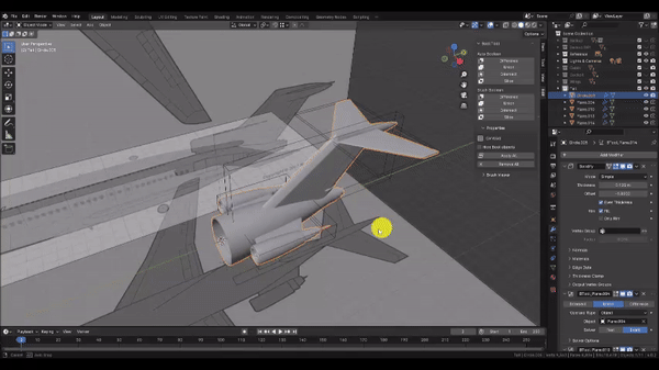
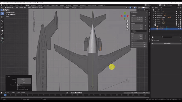
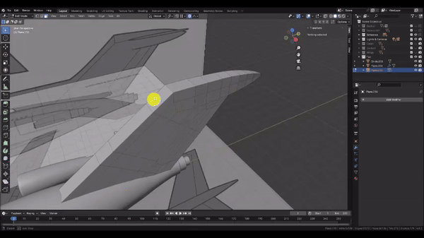
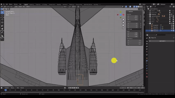
Step 1: Now we’ll create the tail section of the airplane. Since the tail section must join neatly to the cabin section, we’ll copy the outer geometry of the Cabin section to use as the start of the Tail section.
But first, in the Transform Pivot Point Dropdown menu, choose “Median,” then in the Snapping dropdown menu, choose “Center” from the “Snap With” subsection and “Vertex” from the “Snap To” subsection. With these options selected, we’re instructing Blender to snap the Transform Pivot Point of our selection to whichever vertex we hover over. And since we chose “Median” for the Transform Pivot Point, this means the Object Origin will be the snapping point when Grabbing in Object mode.
Now Left Click to select the Cabin section, Duplicate[Shift+D] it, and press Y to lock to the Y axis. Then drag the selection and hold Ctrl to snap Cto any vertex at the end of the cabin array as shown. Left Click to confirm the grab operation.
We’ll also eliminate the modifiers from our copy. Open the Modifiers tab in the Properties panel and click the “X” next to each modifier.
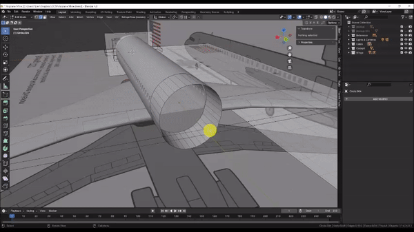
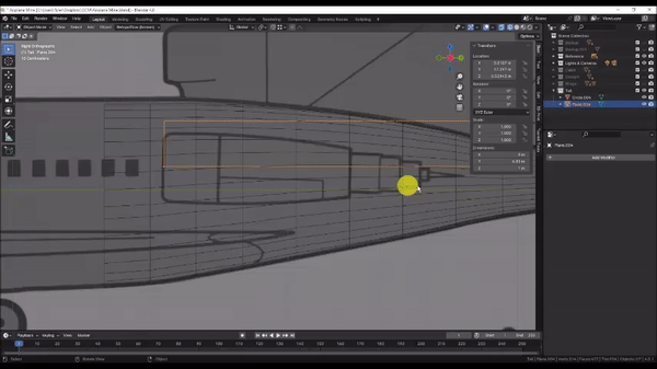
Step 2: We’ll eliminate the interior walls to start with.
Press Tab to enter Edit Mode and orbit the camera around as shown so you can see inside of the mesh. Then hold Shift + Alt + Left Click to select chains of edge loops until the interior edge loops on both ends of the Cabin copy have been selected.
Press Delete and choose Vertices.
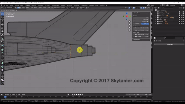
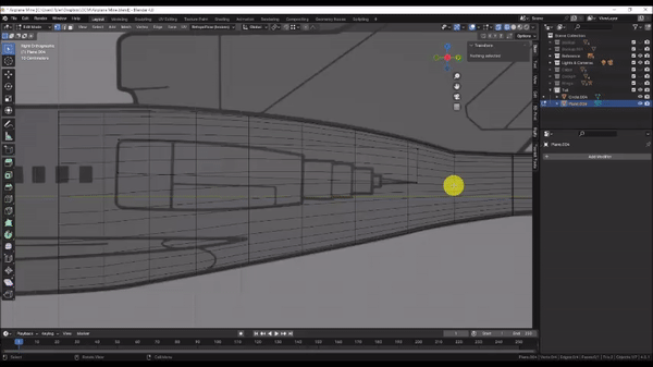
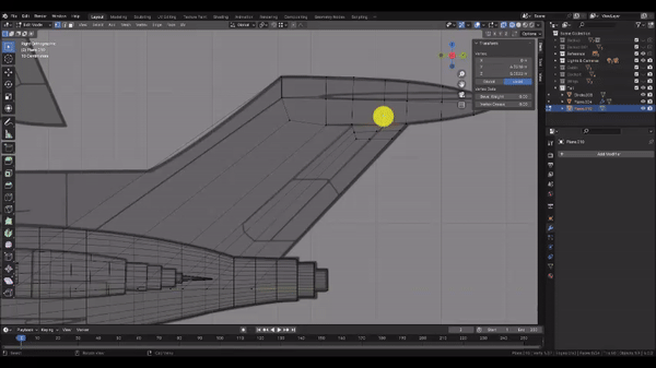
Step 3: Let’s extrude the body of the Tail section.
Press Numpad 3 to snap to the Side Orthographic view, then press Z to change to Wireframe mode.
Hold Alt + Left Click to select the edge loop at the end of the mesh, then use a combination of Extrude[E], Grab[G], Scale[S] and Loop Cut[Ctrl + R] operations to align the mesh with the reference image as shown. We will finish the tip of the Tail section in the next step.
Remember that you can hold Shift while Grabbing, Rotating, or Scaling to achieve finer control over the operation.
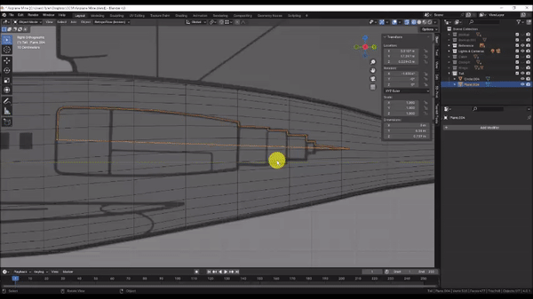
Step 4: Finish the tail section by extruding your our edge loop out to the first step in the stair-step pattern.
Extrude[E] the edge loop, press Esc to cancel the edge slide, then Scale[S] the selection in and Left Click to confirm the Scale operation.
You may or may not find it useful to orbit the camera to a 3D view to better see as you Scale in the edge loops.
Extrude[E] the edge loop, press Y to lock to the Y axis and drag it to the edge of the next stair step.
Extrude[E] the edge loop, press Esc to cancel the edge slide, then Scale[S] the selection in and Left Click to confirm the Scale operation.
Extrude[E] the edge loop, press Y to lock to the Y axis and drag it to the end of the tail in the reference.
Extrude[E] the edge loop again, press Esc to cancel the edge slide. Then, with your edge loop still selected, press M to open the Merge menu, then choose “At Center” to cap off the tail.
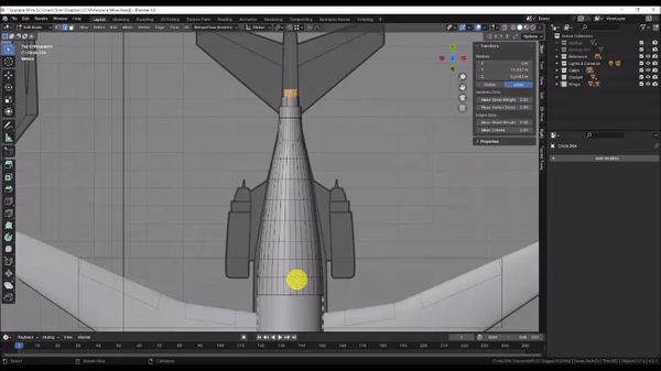
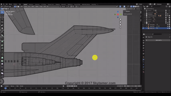
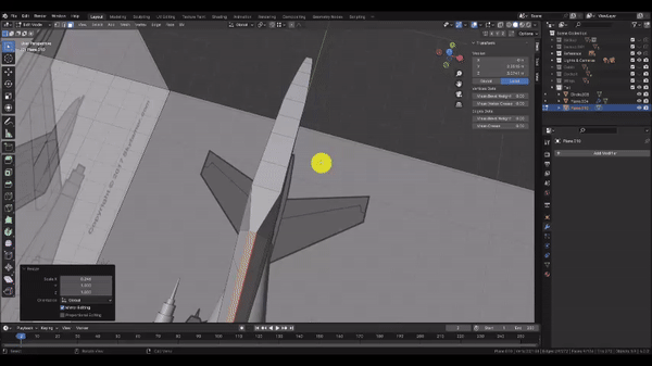
Step 5: Lastly, we’ll make sure the shape conforms to the reference in the top view.
Press Numpad 7 to snap to the Top Orthographic view, then hold Alt + Left Click to select edge loops and Scale[S] them to match the reference. You may find it useful to use Proportional Editing to speed up the process.
When you’re finished, press Tab to exit to Object Mode.
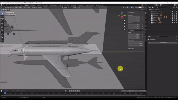
Step 6: Let’s make a new Collection for the Tail.
Left Click to select the Tail section, then press M and choose “New Collection.” Name it “Tail”
In the Outliner, Left Click your new Collection to make it the active Collection. Then Toggle off visibility on the Cabin, Cockpit, & Wings Collections.
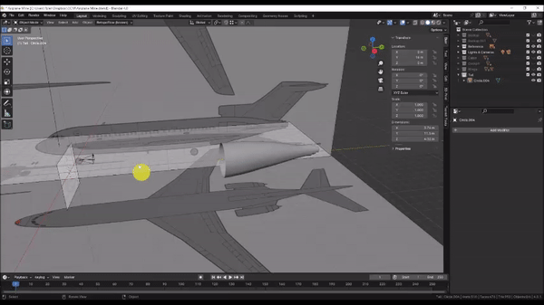
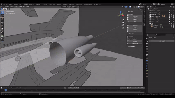
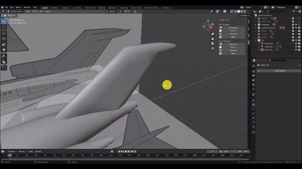
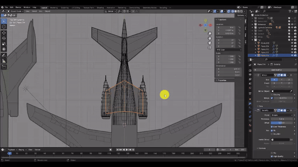
Step 7: Let’s make the engines.
In the “Add” menu, choose Mesh → Plane, then press Tab to enter edit mode, Rotate[R] the selection and press Y to lock to the Y axis. Then enter 90 on the keyboard and press Enter to rotate the plane 90 degrees about the Y axis. Press Tab again to exit to Object Mode.
Press Numpad 7 to snap to the Top Orthographic View, then Grab[G] the selection and drag the plane to the approximate centerline of the engine as shown. Left Click to confirm the grab operation.
Step 8: Press Numpad 3 to snap to the Side Orthographic view, then press Z to change to Wireframe.
You’ll notice that our top and side reference images do not perfectly align. We will defer to the side Orthographic view for the shape of the engine.
Grab[G] the selection once more and position the origin (the small orange dot) of the plane at the front of the engine along the centerline as shown.
Now we will quarter the plane using the Loop Cut tool. Press Tab to enter edit mode, then press Ctrl + R and hover over the right edge of the plane. Left Click to confirm the cut and press Esc to cancel the Edge Slide operation.
Hold Shift + Left Click to select the bottom two vertices, then press Delete and choose “Vertices” to delete them.
Press Ctrl + R, hover over the top edge of the plane and Left Click to confirm the Cut. Then press Esc to cancel the Edge Slide.
Left Click to select the left two vertices, then press Delete and choose “Vertices” to delete them.
Hold Shift + Left Click to select the right two vertices, then Grab[G] them, press Y to lock to the Y axis, and drag them past the pointed tip of the engine as shown.
Press Tab to exit to Object Mode.
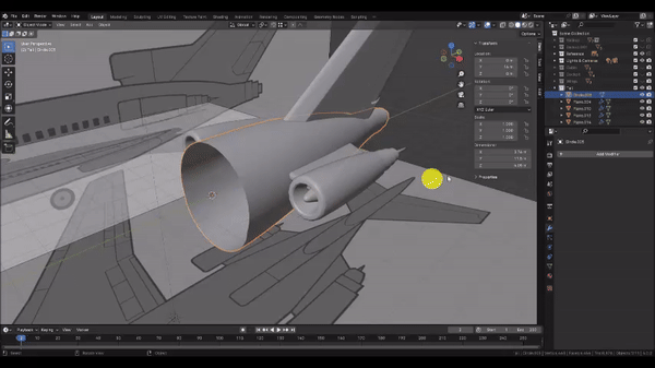
Step 9: The rear of the engine is pitched slightly toward the ground. We could simply trace the shape in Edit Mode to match this pitch, but when a whole object is rotated out of level with the XYZ axes, it’s usually a better idea to perform the rotation in Object Mode instead. This allows us to maintain symmetry and alignment within the object. In our case, we will be using the Screw Modifier, which works similar to a lathe tool and allows us to create complex profiles about a central axis. For this to work correctly, we need to align the Y axis of our object with the central axis of the engine.
Rotate[R] the selection and align the bottom edge with the central axis of the engine as shown.
Another benefit of performing the rotation in Object Mode is that we can take advantage of both the Global and Local coordinate systems for our XYZ axis snapping. The Local coordinate system refers to the orientation of XYZ space as modified by an Object’s Transform properties. For example, In the Global Coordinate System, the point x=0, y=0, z=0 is the center of our scene. However, for an Object whose X Location value is 1, the point x=0, y=0, z=0 in the Local coordinate system would be offset by 1 unit in the X direction, relative to the Global Coordinate System. And the same principle applies to Rotation and Scale values as well. Although the engine appears at a slight angle in the Global Coordinate System, the mesh is still aligned horizontally and vertically in its Local Coordinate System. This means that we can lock our operations to the local XYZ axes to keep the geometry aligned with the reference.
Press Tab to enter Edit Mode, then hold Shift + Left Click to select the top two vertices. Grab[G] the selection, then press Z to lock to the (Global) Z axis. Press Z once more to lock to the Local Z axis instead. This will allow us to drag the vertices in parallel with the central axis of the engine. Drag the selection to align with the top edge of the engine as shown. Left Click to confirm the Grab operation.
Hold Shift + Left Click to select the right two vertices, then Grab[G] the selection, press Y to lock to the (Global) Y axis. Press Y once more to lock to the Local Y axis instead. Drag the selection to the tip of the engine as shown.
Step 10: Use the knife tool to trace the upper half of the engine as shown.
Press K to activate the Knife tool, then Left Click along each point. Press Enter to confirm the cut.
Left Click to select the left corner vertex and press Ctrl + B to activate the Bevel command. Then press V to enable Vertex Mode, and drag to bevel the corner. Scroll with the Mouse Wheel to adjust the number of vertices to create. Add 4 vertices to round the corner and match the reference.
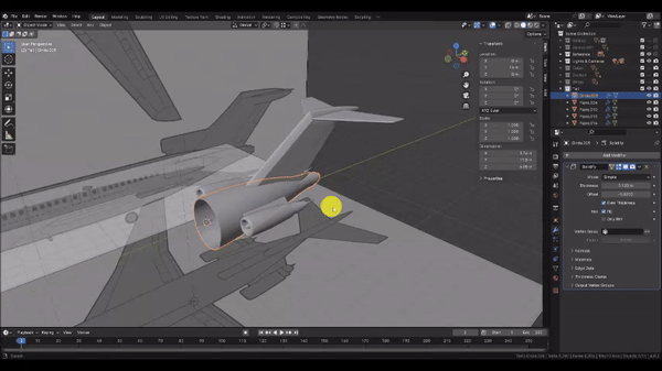
Step 11: Now we’ll create a solid shape from this profile.
Press Tab to exit to Object Mode and orbit the camera to a 3D view.
In the Modifiers tab of the Properties panel, choose Add Modifier → Generate → Screw
In the Screw Modifier, change the Axis to Y. You can adjust the density of the rounded shape by changing the “Steps Viewport” Value. I will keep the value at 16 for now.
In the modifiers panel choose Add Modifier → Generate → Mirror. It may look as though nothing happened, because by default the Mirror Modifier uses the object’s origin point to establish the axis of symmetry, and our object is already symmetrical about the origin. Fortunately, the mirror modifier lets us borrow the origin point of another object to use for the axis of symmetry instead.
In the Mirror Modifier, click the eye dropper icon in the “Mirror Object” box. Then Left Click on the body of the Tail section in the viewport to set it as the Object to mirror about.
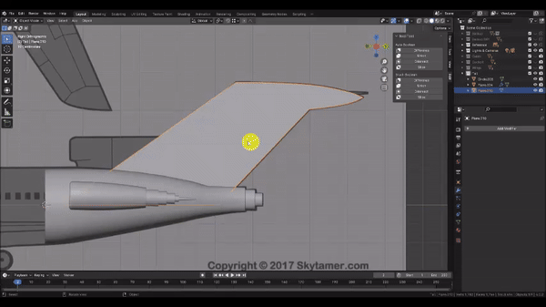
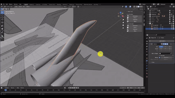
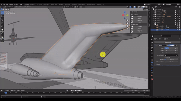
Step 12: Now we’ll create the tail fin. Left Click to select the Tail section, then press Shift + S and choose Cursor to Selected. Press Numpad 3 to snap to the Side Orthographic view.
In Object Mode, click Add → Mesh → Plane to insert a plane, then press Tab to enter Edit Mode
With the mesh selected, Rotate[R] the selection, press Y to snap to the Y axis, then enter 90 on the keyboard and press Enter to rotate the selection 90 degrees about the Y axis.
Press Tab to exit Object mode, Press Z to switch to Wireframe Mode, then Grab[G] the selection, press Y to lock to the Y axis, and drag it back to roughly the middle of the base of the Tail Fin. Left Click to confirm the grab operation. Then press Tab to enter Edit Mode once again.
Step 13: Our reference image doesn’t give us adequate information to model the middle engine that blends into the front of the tail fin, so we will ignore it for this exercise.
Press Ctrl + R to activate the Loop Cut command and hover over the right edge of the plane mesh. Left Click to confirm the cut and press Esc to cancel the edge slide.
Left Click, hold and drag to draw a selection box around the bottom two vertices to select them. Then press Delete and choose “Vertices” to delete the lower half of the plane mesh
Grab[G] and move the remaining edges and vertices as shown to trace the leading edge of the tail fin, excluding the center engine.
Step 14: We’ll begin tracing the shape of the tail fin as well as some of the interior edges. Remember that ideal topology for subdivision surface modeling consists entirely of 4-sided geometry (or Quads).
Press K to activate the Knife tool and Left Click at each point to insert vertices as shown. When you’re finished with a cut, press enter to confirm the Knife operation.
Be sure to include the interior edge parallel to the leading edge of the Tail Fin, as we will need this to create the taper.
Step 15: Continue using the Knife[K] tool to add edges and vertices as shown. Notice how we cut diagonally from the top left corner of the Tail flap. We do this so that the extra edges we add to capture the shape of the bottom left corner of the rudder don’t have to be carried through out the top of the fin, which would create undesirable mesh density in that area. Instead we can divert those edges out the back and still maintain 4-sided geometry and proper edge flow.
Step 16: Use the Knife[K] tool to cut in the bottom edge of the rudder. Finalize the mesh by ensuring your vertices align well with the reference. Where possible, make your 4-sided faces as uniform as possible.
Use the Knife[K] tool to cut additional edges from the bottom left corner of the rudder and across the entire Tail Fin as shown below to make the remaining geometry 4-sided.
When you’re finished, press Tab to exit to Object Mode, then press Z to change to Solid Shading mode.
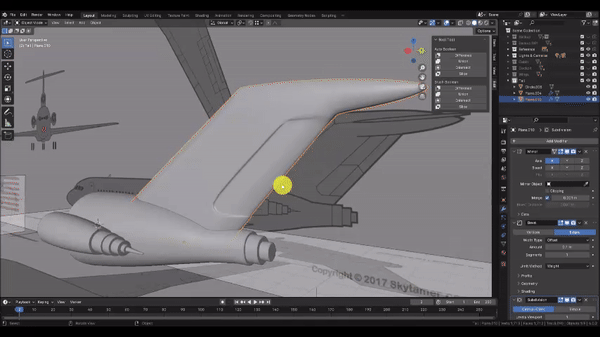
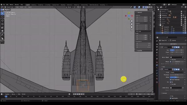
Step 17: Now we’ll create a solid shape from this profile.
In Object Mode, under the Modifiers tab of the Properties panel, choose Add Modifier → Generate → Solidify. Then set the “Offset” value to 0, check the “Even Thickness” box, and under the “Normals” subsection, check the “High Quality” box as well.
Now press Numpad 7 to snap to the Top Orthographic view. then Left Click and Drag to the right on the “Thickness” value until the thickness of your mesh matches the thickness of the Tail Fin in the reference at its widest point as shown.
When you’re satisfied, click the small down arrow button near the top of the Solidify Modifier and choose apply.
Step 18: Now we’ll taper the mesh towards the end of the Tail. Press Tab to enter Edit Mode, then press Z to go into Wireframe mode.
Press O to enable Proportional Editing, then switch to Edge Selection Mode. Left Click to select the back edge of the mesh, Scale[S] the selection, press X to lock to the X axis, then drag in towards the center of the screen until it matches the reference. Scroll with the Mouse Wheel while Scaling to adjust the falloff radius on the proportional editing and achieve the desired result. Left Click to confirm the Scale operation.
If necessary, you may repeat this process on other edges along the length of the Tail Fin to better match the reference. Be sure to Lock to the X axis when scaling to avoid unwanted changes to the mesh profile.
Step 19: Next we’ll add the taper to the front and back edges of the Tail Fin. First, Switch to Face Select Mode and press O to disable Proportional Editing.
Hold Shift + Left Click to select the faces that represent the front edge of the Tail Fin as shown. Then Hold Shift + Left Click to select the faces that represent the back edge of the Tail Fin. You may need to temporarily hide the Tail section or switch to Wireframe to select the faces obscured by the tail section.
Scale[S] the selection, press X to lock to the X axis, and drag towards the center of the screen as shown. Left Click to confirm the scale operation.
Step 20: We need to blend the flat top edge of the Tail Fin into a more rounded shape as it narrows to a point. We’ll start this process by scaling in the top and bottom edges, roughly following the curvature of the taper we added earlier. Although we could accomplish this by masking our selection and using proportional editing, in this case, it may be faster to perform the work manually.
For each edge, Left Click to select it, then Scale[S] the selection, and drag towards the center of the screen as shown. Left Click to confirm the Scale operation.
You can attempt to match them by eye, but If you want to match the bottom edges of the Tail Fin tip precisely with the top edges, Left Click the “Snapping” dropdown menu, and choose the following options:
Snap With = Closest
Snap To = Vertex
Affect = Make sure Move, Rotate, & Scale are all highlighted
With those snapping options set, while scaling a bottom edge, hold the Ctrl key and hover over a vertex belonging to the corresponding top edge until you see the orange box indicating a successful vertex snap. Be sure to lock to the X axis while scaling. Left Click to confirm the Scale operation.
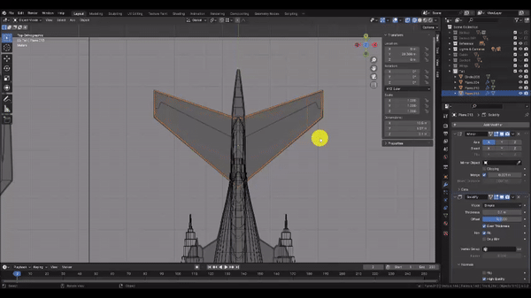
Once you’re finished, press Tab to exit to Object Mode, then Right Click in the Viewport to bring up the Object menu and choose “Shade Smooth.” This will help us better visualize the rounded tip of the Tail Fin.
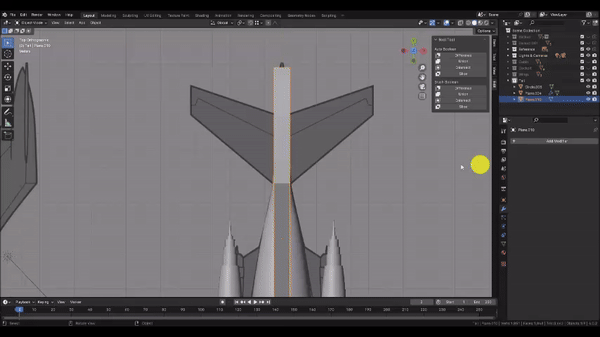
Step 21: Next, we’ll prepare the mesh for a Mirror Modifier by adding a centerline. With your Fin Selected, press Tab to enter Edit Mode once again.
Press Ctrl + R and hover over a horizontal edge as shown, to propagate a centerline Loop Cut around our entire mesh. Left Click to confirm the cut, then press Esc to cancel the edge slide. If it takes more than one Loop Cut operation to add an edge loop around the entire mesh, it means you have non-quad geometry somewhere.
Once you have your centerline, press Numpad 7 to snap to the Top Orthographic view, then press Z to change to Wireframe mode and switch to Vertex Select Mode as well.
Step 22: To prevent overlapping faces and bad geometry, we’ll need to split the mesh in half before mirroring. Be sure you have the entire tail fin in view.
Hold Left Click & Drag and very carefully drag a box around all of the vertices on the left side of the Tail Fin. Make sure not to select any of the vertices along the centerline or on the right side. It may take a few tries to get the selection right.
Press Delete and choose “Vertices” to delete the left entire side of the Tail Fin. Then press Tab to exit to Object Mode, press Z to change back to Solid Shading, and orbit the camera to a 3D view.
Now we’ll add a Mirror Modifier. This ensures that any work we perform on one side of the mesh will automatically apply to the opposite side.
In the Modifiers tab of the Properties panel, choose Add Modifier → Generate → Mirror. If you notice gaps or overlapping geometry, it likely means that your centerline is not perfectly uniform along the X axis. You can fix this by selecting all of the centerline vertices. Change your Transform Pivot Point to 3D cursor, then Scale[S] the selection, press X to lock to the X axis, and enter 0 on the keyboard for the scale factor. Press Enter to Confirm the Scale operation and change your Transform Pivot Point back to Median.
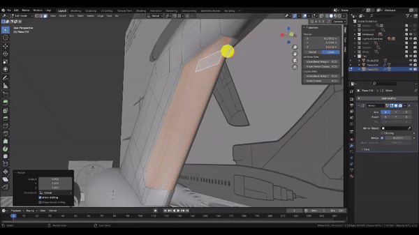
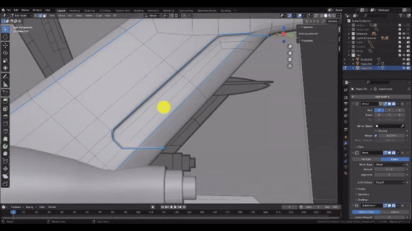
Step 23: Now we’ll add an inset feature to represent the Tail Flap. Press Tab to enter Edit Mode once again, then switch to Face Select Mode and change the Transform Pivot Point to 3D Cursor.
Hold Shift + Left Click to Select all of the faces that represent the Tail Flap as shown, including the back edge, and press i to activate the Inset Faces command.
Because we split our base mesh in half, the centerline of our Tail Flap is now technically the edge of the base mesh. By default, the Inset Face command will therefore treat it as the edge of the selection and create undesirable geometry at that location. With the Inset Face command still active, Press B to toggle the “Boundary” option. This tells Inset faces to ignore the edge of a mesh when creating boundary geometry, which will direct our edge flow around to the opposite side where we want it to go.
Drag the mouse very slightly towards the center of the screen as shown. Left Click to confirm the Inset Faces operation.
Now, Scale[S] the selection, press X to lock to the X axis, and drag the mouse in towards the center of the screen as shown.
Finally, Hold Shift + Left Click to select the faces that represent the back edge of the Tail Flap, then Grab[G] the selection, press Y to lock to the Y axis, and drag in towards the front of the Tail Fin as shown in the second clip.
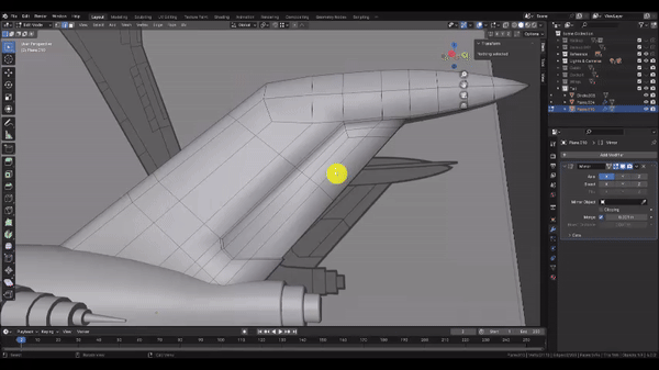
Step 24: Adding the centerline to our mesh gave us some additional geometry to work with to further blend the end of our tail into a more rounded form.
Switch to Edge Select Mode, then Hold Shift + Left Click to select the sharp edges on the top and bottom as shown. Then Scale[S] the selection, press Z to lock to the Z axis, and drag the mouse in towards the center of the screen to achieve a rounder shape. Remember that the Mirror Modifier is handling the opposite side of the mesh for us.
Now Left Click to select and Grab[G] individual vertices to more gradually blend the rounded shape into the sharp top edge of the Tail Fin as shown. Note that if you press G a second time after activating the Grab Operation, you can lock the selection into an edge slide operation. This is a particularly helpful way to move vertices for this application.
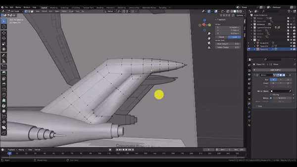
Step 26: Now that we’ve finished with the main features of our Tail Fin, let’s refine things further. You may have noticed that applying smooth shading to the model removed the harsh edges, but left us with this rather indistinct and unappealing shading. To fix this, we have to add what are called Supporting Edge Loops at all of our sharp edges. We could use individual Bevel operations to achieve this, but our topology is becoming complicated, and this could easily make a mess of things.
Instead, we’ll use a Bevel Modifier so that we can add this extra geometry in a more controlled non-destructive fashion. But for the Bevel Modifier to work properly, we have to indicate which edges to Bevel by using the “Bevel Weight” property up in the “Item” Tab near the Outliner.
Hold Shift + Left Click to select all of the sharp edges as shown. Don’t forget to get inside the corners of the Tail Flap.
Once you have all of the desired edges selected, under the “Edge Data” heading, set the “Bevel Weight” value to 1
When you’re finished, press Tab to exit to Object Mode.
Step 25: Now we’ll add our modifiers.
In the Modifiers tab of the Properties panel, choose Add Modifier → Generate → Bevel
In the Bevel modifier, set the “Limit Method” to “Weight” and the “Segments” to 2.
We’ll add a Subdivision Surface Modifier as well.
At the top of the Modifiers window, choose Add Modifier → Generate → Subdivision Surface
You should see a marked improvement in the shading of your mesh. If you see any sharp edges that aren’t properly beveling, you can go back and select them and set the “Bevel Weight” value of those edges to 1.
Note that our Bevel modifier is creating a lot of triangular faces at the points where the Bevel flow terminates. However, since the main purpose of maintaining 4-sided topology is to prevent shading artifacts, if the shading looks good, then the topology is acceptable.
Step 26: The Tail Fin is almost complete, but in my case, I’m not entirely happy with how much rounding is occuring at the top and bottom left corners of my Tail Fin Inset. To Address that, I use the Loop Cut[Ctrl+R] tool to add supporting edges, which I drag close to my problem areas until the Subdivision geometry noticeably improves.
When you’re done, press Tab to exit back to Object Mode.
Step 27: Let’s create the Stabilizer Fin. Press Numpad 7 to snap to the Top Orthographic view.
In the Add menu, choose Mesh → Plane. Then press Tab to enter edit mode on the newly created plane and press Z to change to Wireframe mode.
Now we’ll remove the left half of the mesh to prepare it for a Mirror Modifier. Press Ctrl + R and hover over the bottom edge. Left Click to confirm the cut and press Esc to cancel the Edge Slide operation. Hold Left Click and drag to box select the left vertices, press Delete, and choose “Vertices.”
Press Tab to exit to Object Mode.
Step 28: Next we’ll add several Modifiers. In the Modifiers tab of the Properties panel, add the following:
a Mirror Modifier to keep the mesh symmetrical
a Solidify Modifier to give it thickness
a Bevel Modifier to round and add Supporting Edge Loops to the edges
a Subdivision Surface Modifier
Remember that the order in which Modifiers appear in the Modifiers Panel (or Modifier Stack) determines the order in which Blender will carry out these operations, which can affect the final result. For example, if the Subdivision Surface operation were to be occur before the Bevel operation, it would smooth the entire virtual mesh, leaving no sharp edges for the Bevel Modifier to work on.
Once you’ve added these modifiers, we will edit a few of their properties.
In the Solidify Modifier, set the “Offset” value to 0, then check the “Even Thickness” box and under the “Normals” Subsection, check the “High Quality” Box.
In the Bevel Modifier, change the “Segments” value to 2.
Step 29: Now we’ll match the Stabilizer geometry to the reference.
Grab[G] the selection, press Y to lock to the Y axis, and drag until the object is roughly centered on the Stabilizer in the reference. Left Click to confirm the Grab operation, then Press Tab to enter Edit Mode.
Use Left Click to select each vertex, then Grab[G] it and drag it over to match the reference as shown. Left Click to confirm the Grab operation, then press Tab to exit to Object Mode.
Step 30: Next we’ll match the Stabilizer to the Side Reference. Press Numpad 3 to snap to the Side Orthographic view.
Grab[G] the selection, press Z to lock to the Z axis, then drag it up until it aligns with the vertical position of the Stabilizer in the reference. The Reference images don’t align perfectly, so defer to whichever position looks best to you. Left Click to confirm the Grab operation, then Press Z to change to Solid Shading mode.
In the Solidify Modifier, Left Click and Hold the “Thickness” value, then drag to the right to adjust the value until it matches the reference.
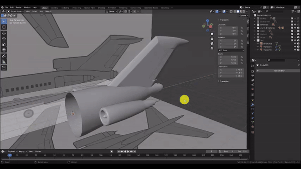
Step 31: Now we’ll create the flanges that join the engines to the body of the Tail section. Press Numpad 7 to snap to the Top Orthographic view.
Since we’ll be using the same set of Modifiers for the flange piece, we’ll just duplicate the Stabilizer as a starting point.
Duplicate[Shift+D] the selection, press Y to lock to the Y axis, and drag the duplicated Stabilizer until it’s roughly centered over the flanges as shown. Left Click to confirm the Grab operation, then press Z to switch to Wireframe mode and press tab to enter Edit Mode.
Use Left Click to select each vertex, then Grab[G] it and drag it over to match the reference as shown. Left Click to confirm the Grab operation, then press Tab to exit to Object Mode.
Step 32: Let’s align the Flange roughly to the centerline of the engines. Press Numpad 3 to snap to the Side Orthographic view.
Grab[G] the selection, press Z to lock to the Z axis, then drag it down until it aligns with the engine centerline in the reference. You will also have to Rotate[R] the selection to match the pitch of the engines.
Once you’ve done this, orbit the camera to a 3D view and press Z to switch to Solid Shading. Then in the Solidify Modifier, increase the “Thickness” value to 0.3.
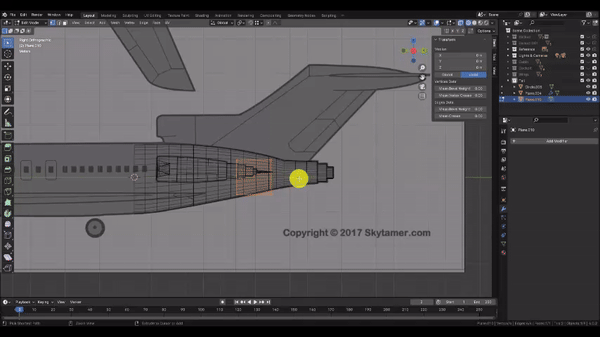
Step 33: We’re almost ready to finalize the Tail section. But first we have to add a thickness to the Tail body.
Left Click to select the Tail body, then in the Modifiers tab of the Properties panel, choose Add Modifier → Generate → Solidify.
Check the “Even Thickness” box and in the “Normals” subsection, check the “High Quality” box. Then, change the “Thickness” value to 0.07.
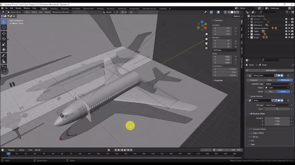
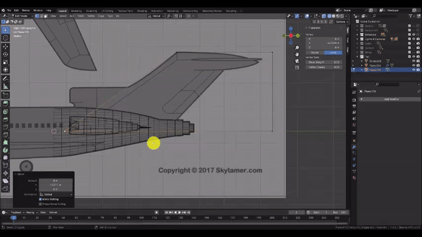
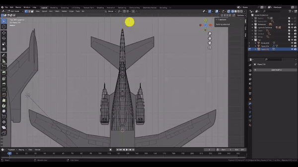
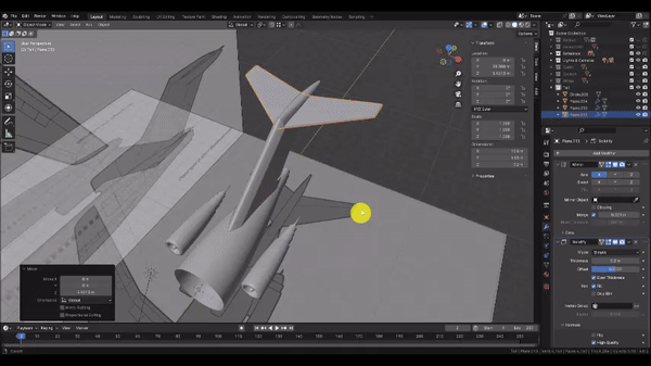
Step 33: We can now merge all of our parts into a single mesh.
Hold Shift + Left Click each part. Be sure to select the Tail body last:
the Tail Fin
the Stabilizer
the Engines
the Flange
the Tail body
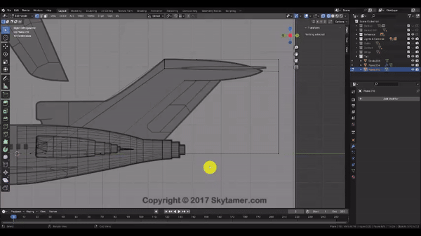
In the “Edit” menu near the Outliner, under the “Brush Boolean” subsection, choose “Union.” This will fuse all of the parts together into a single mesh without overlapping geometry.
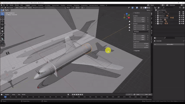
Step 33: Let’s see the final result.
In the Outliner, Left Click the eye icon to toggle on visibility for the Wings, Cabin, and Cockpit collections, and toggle off visibility for the Reference collection. Lastly, Left Click the “Show Overlays” button to toggle off visibility on UI objects in your scene such as the coordinate grid, Boolean Objects, Lights & Cameras.
You can also press Z to change to Rendered Mode for higher quality lighting.