Shader Nodes
Years:
Material Shading:

Graphics Programming is an extremely technical discipline, which relies on complex mathematical formulae and computer code to efficiently color screen pixels, creating sophisticated patterns and motion. Blender’s Material Shader is a user interface that allows you to point and click to modify these computations. Although this interface greatly simplifies the process, the concepts and parameters involved are still highly complex and technical. Fortunately, even if you are not mathematically inclined, with experience and experimentation, you can still develop an intuitive understanding of the process and learn to create truly impressive rendering materials. Below are some of the most commonly used Shader Nodes that you will use to create materials.
Common Shader Nodes:
A Brief Explanation of Shader Nodes:
Shader Nodes like the “Principled BSDF” shader shown below are user controls that you connect together in sequence to construct the logic and data inputs that the rendering engine will use to color a 3D object. The small dots on the left and right edges of the node represent the inputs (left) and outputs (right). They are color-coded based on the data type: gray represents numbers, yellow represents colors (a set of 4 numbers - the first 3 range from 0 to 255 and represent the Red, Green, and Blue color channels (RGB). The last number ranges from 0 to 1 and represents the light / dark value of the color), blue represents vectors, (a set of 3 numbers, such as an x, y, z coordinate), and green represents shaders. You can connect Shader Nodes by clicking and dragging on an output and then dragging the resulting line over to the input of another node. With some exceptions, outputs and inputs must be of compatible types to function correctly.
Additionally, many nodes provide input controls, corresponding to the data type, that allow the user to modify the default value of the input. For example, in the below “Principled BSDF” shader, the “Base Color” input is yellow, indicating that it’s a color input, so the user is provided with a color picker box to set the default value. Since the “Metallic” input is gray, indicating that it’s a number input, the user is instead provided with a text box to enter a number. In some cases, number values may be “normalized,” meaning that they only accept values from 0 to 1 (think 0 to 100 percent).
The order of operations for the Shader tree is determined by the input / output connections of your nodes - not their position on the screen. You’re free to click and drag the node header or Grab[G] to move the selection around and organize the nodes however you want within the Shader Editor’s workspace.
Principled BSDF (Add → Shader):
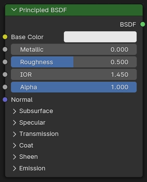
The Principled BSDF shader is the main data input for most of the materials you’ll create, and is added by default whenever you create a material. It implements what’s known as the “Physically Based Rendering” (PBR) shading algorithm, which incorporates parameters from real world physics and optics and material science to generate visually accurate results on screen. Below is an explanation of the inputs:
Base Color: represents the true color of the object, absent any lighting effects.
Metallic: switches between different sets of light interactions. This is a binary attribute and should only be set to 0 for non-metals or 1 for metals.
Roughness: represents the clarity of reflections on a surface. Low roughness values create shiny, more mirror-like surfaces.
IOR: represents the Index of Refraction of the material. This is a real world physical property that measures the rate of falloff in reflectivity. IOR values for common materials may be available online.
Alpha: represents the Opacity of the material. Transparent materials such as glass will have lower Alpha values. A material with an Alpha value of 0 becomes invisible.
Subsurface: simulates the scattering of light within a translucent volume, such as human skin. Consider how the coloration of your hand is affected when you hold it close to a flashlight. This visual effect is an example of subsurface scattering.
Specular: represents how reflective a surface is. Higher specular values make a surface more reflective.
Transmission: represents the translucency of a surface. A translucent surface allows light to pass through it without necessarily being transparent. A leaf is an example of a translucent surface.
Coat: is a specialized property used to simulate a clear-coated surface such as car paint.
Sheen: is a specialized property used to simulate light effects that occur in micro-fibrous surfaces such as clothing or velvet.
Emission: allows the surface to emit light. You can use this to simulate light sources such as colored LED’s or bioluminescence.
Texture Mapping Nodes:
A Brief Explanation of UV Unwrapping and Texture Coordinate Mapping:
The graphics engine colors 3D objects by extracting the coordinates of pixels on a flat image texture and then projecting them to the 3D surface according to that object’s UV Map. A UV Map is a flattened representation of the 3D object. You can visualize this by imagining that the faces in the object’s mesh are separated and unfolded into a flattened state like Origami. Hence, to color the cube below, the texture image would be colored exactly as shown in the cube’s flattened state.
Texture Coordinate (Add → Input):
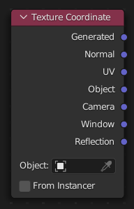
The Texture Coordinate node determines the source coordinates that will be used by the textures in your shader tree. For our purposes, the most important options are:
Generated: Blender will automatically generate a UV map for whichever object the material is applied to. This is the preferred option to use when working with procedural textures.
UV: Blender will use the active user-generated UV map for whichever object the material is applied to. This is the preferred option when working with image textures.
Mapping: (Add → Vector):
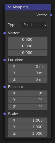
The Mapping node allows you to modify a vector’s location, rotation, and scale. This is most commonly used to modify a set of Texture Coordinates.
Normal Map (Add → Vector):
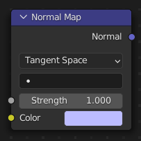
The Normal Map node converts an image texture representing a normal map into a format recognized by the renderer, and allows the user to adjust the intensity of the effect. Normal Maps override the normal direction of the faces in a mesh, essentially tricking the renderer into interpreting the shape differently for the purposes of lighting, reflections, and other important rendering calculations. The most common use for Normal Maps is to fake curvatures or subtle 3-dimensional shapes that would be too onerous or resource intensive to model or render. For example, rather than modeling every pebble in a gravel path, a normal map can be used to give the impression of thousands of pebbles that the light interacts with as though they were 3D.
Texture Nodes:
A texture is simply a digital image comprised of colored pixels, typically stored in the .JPG or .PNG file format. A picture you take on your phone or find online, an MS Paint drawing, or an image generated procedurally by Blender can all be used as Textures in the Shader Editor. All texture nodes must receive input from a Texture Coordinate Node to work properly.
Image Texture (Add → Texture):
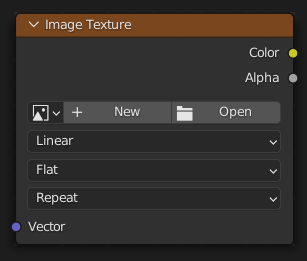
The Image Texture node allows you to upload a digital image to use in the Shader Editor. You will typically use this in conjunction with the UV output of a Texture Coordinate node. This node provides you with some standard projection modes such as Cube and Sphere, which may eliminate the need for UV unwrapping.
Gradient Texture (Add → Texture):

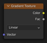
The Gradient texture generates a black and white image which gradually transitions from one color to the other along a single axis.
Wave Texture (Add → Texture):

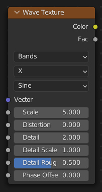
The Wave texture generates a black and white image of alternating bands or rings. Using this texture with distortion can be an effective way to achieve a procedural wood grain pattern. Note that the appearance of this texture can vary widely depending on how its various input parameters are set.
Noise Texture (Add → Texture):

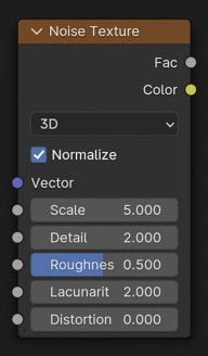
The Noise Texture generates either a black and white or color image of quasi-random values. This is one of the most commonly used procedural textures. Note that the appearance of this texture can vary widely depending on how its various input parameters are set.
Voronoi Texture (Add → Texture):

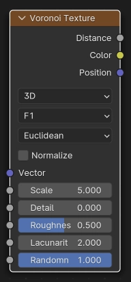
The Voronoi Texture generates either a black and white or color image of bounded shapes. This texture offers some of the widest variety of patterns. Note that the appearance of this texture can vary widely depending on how its various input parameters are set.
Musgrave Texture (Add → Texture):

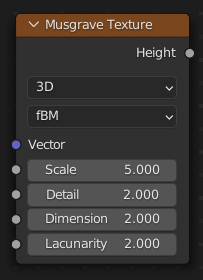
The Musgrave Texture generates a black and white image of various patterns. Note that the appearance of this texture can vary widely depending on how its various input parameters are set.
Other Useful Nodes:
Color Ramp (Add → Converter):
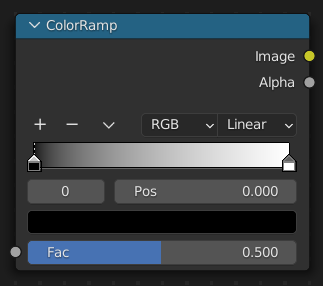
The Color Ramp node assigns colors to incoming values based on where that value falls on a 0 to 1 scale. Although the input data type is a number value, you can also plug grayscale or color data into this node, and it will assign colors based on the light / dark value of the color input. This is an extremely useful function; as you can see above, by moving the white color slider so that it almost touches the black, I am recoloring all but the darkest pixels to white, which creates an effect that resembles hairline cracks. You can also create as many additional sliders as you want and assign different colors to them to create interesting and colorful effects.
Mix Color (Add → Color):
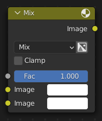
The Mix Color node blends two color inputs together weighted by a 0 to 1 “Factor” slider. It is an essential tool for layering visual effects to produce a believable material, and offers several different methods for blending.
Hue Saturation Value (Add → Color):
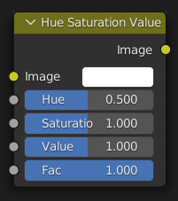
The Hue Saturation Value (HSV) node allows you to adjust the RGB and light / dark values of the incoming color data in a way that’s more intuitive than dealing with raw RGB values. “Hue” refers to the overall color (red, green, blue, etc.), “Saturation” refers to how vibrant or washed out the color is, and “Value” refers to how light or dark the color is.
Invert Color (Add → Color):
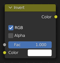
The Invert Color node inverts the RGB and light / dark values of an incoming color input. This is especially helpful when working with black and white masks.
Bump (Add → Vector):
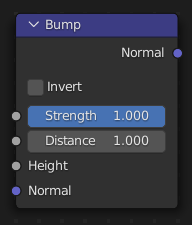
The Bump Node reinterprets the light / dark values of a color input to add artificial depth to a shader output. Unlike the Normal Map, the Bump node’s depth illusion does not interact with light, and appears noticeably flat when viewing the surface at an angle. It is best used for very small details or background objects.
Math (Add → Converter):
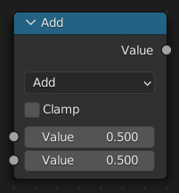

The Math Node performs mathematical operations on various inputs. It is especially useful for complex logic and automation.
Value (Add → Input):
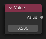
The Value node allows you to input any number to use with other nodes. It is especially useful for complex logic and automation. For example, if you need to use the same numerical inputs in several different nodes, you can connect them all to the Value node, allowing you to change all 3 inputs at once.
RGB (Add → Input):
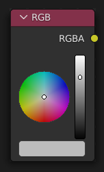
The RGB node allows you to input any color to use with other nodes. It is especially useful for complex logic and automation. For example, if you need to use the same color as inputs in several different nodes, you can connect them all to the RGB node, allowing you to change all 3 inputs at once.